
Going Really Deep
Contents
Going Really Deep#
If all you need to do is design the circuitry for a PCB, then you probably know all the SKiDL you need to know. This section will describe the features of SKiDL that might be useful (or not) to some of the avant-garde circuit designers out there.
Circuit Objects#
Normally, SKiDL puts parts and nets into a global instance of a Circuit object called default_circuit (which, of course, you never noticed). But you can create other Circuit objects:
>>> my_circuit = Circuit()
and then you can create parts, nets and buses and add them to your new circuit:
>>> my_circuit += Part("Device",'R')  # Add a resistor to the circuit.
>>> my_circuit += Net('GND')          # Add a net.
>>> my_circuit += Bus('byte_bus', 8)  # Add a bus.
In addition to the += operator, you can also use the methods add_parts, add_nets, and add_buses. (There’s also the much less-used -= operator for removing parts, nets or buses from a circuit along with the rmv_parts, rmv_nets, and rmv_buses methods.)
You can also place parts, nets, and buses directly into a Circuit object by using the circuit parameter of the object constructors:
>>> my_circuit = Circuit()
>>> p = Part("Device", 'R', circuit = my_circuit)
>>> n = Net('GND', circuit = my_circuit)
>>> b = Bus('byte_bus', 8, circuit = my_circuit)
Alternatively, you can use a context manager inside of which a Circuit object becomes the default_circuit:
my_circuit = Circuit()
with my_circuit:
    p = Part('Device', 'R')
    n = Net('GND')
    b = Bus('byte_bus', 8)
Hierarchical circuits also work with Circuit objects. In the previous multi-level hierarchy example, the subcircuit could be instantiated into a Circuit object like this:
my_circuit = Circuit()   # New Circuit object.

gnd = Net('GND')         # GLobal ground net.
input_net = Net('IN')    # Net with the voltage to be divided.
output_net = Net('OUT')  # Net with the divided voltage.
my_circuit += gnd, input_net, output_net  # Move the nets to the new circuit.

# Instantiate the multi-level hierarchical subcircuit into the new Circuit object.
multi_vdiv(3, input_net, output_net, circuit = my_circuit)
The actual circuit parameter is not passed on to the subcircuit. It’s extracted and any elements created in the subcircuit are sent there instead of to the default_circuit.
Hierarchy is also supported when using a context manager:
my_circuit = Circuit()

with my_circuit:
    # Everything instantiated here goes into my_circuit.
    gnd = Net('GND')
    input_net = Net('IN')
    output_net = Net('OUT')
    multi_vdiv(3, input_net, output_net)
You can do all the same operations on a Circuit object that are supported on the default circuit, such as:
# Check the circuit for errors.
my_circuit.ERC()

# Generate the netlist from the new Circuit object.
my_circuit.generate_netlist(sys.stdout)
Naturally, the presence of multiple, independent circuits creates the possibility of new types of errors. Here are a few things you can’t do (and will get warned about):
You can’t make connections between parts, nets or buses that reside in different Circuit objects.
Once a part, net, or bus is connected to something else in a Circuit object, it can’t be moved to a different Circuit object.
Generating a Schematic#
Although SKiDL lets you avoid the tedious drawing of a schematic, some will still want to see a graphical depiction of their circuit. To this end, SKiDL can show the interconnection of parts as a directed graph using 1) the graphviz DOT language or 2) as a more traditional schematic using SVG.
The following circuit will be used to illustrate both methods:
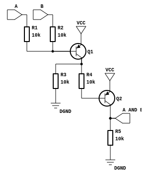
The SKiDL script for this circuit is:
from skidl import *

# Create part templates.
q = Part(lib="Device.lib", name="Q_PNP_CBE", dest=TEMPLATE, symtx="V")
r = Part("Device", "R", dest=TEMPLATE)

# Create nets.
gnd, vcc = Net("GND"), Net("VCC")
a, b, a_and_b = Net("A"), Net("B"), Net("A_AND_B")

# Instantiate parts.
gndt = Part("power", "GND")  # Ground terminal.
vcct = Part("power", "VCC")  # Power terminal.
q1, q2 = q(2)
r1, r2, r3, r4, r5 = r(5, value="10K")

# Make connections between parts.
a & r1 & q1["B", "C"] & r4 & q2["B", "C"] & a_and_b & r5 & gnd
b & r2 & q1["B"]
q1["C"] & r3 & gnd
vcc += q1["E"], q2["E"], vcct
gnd += gndt
DOT Graphs#
Note: Viewing DOT files requires that you install graphviz on your system.
To generate a DOT file for the circuit, just append the following to the end of the script:
generate_dot(file_='and_gate.dot')
After running the script to generate the and_gate.dot file, you can transform it into a bitmap file using the command:
$ dot -Tpng -Kneato -O and_gate.dot
The resulting and_gate.dot.png file looks like this:
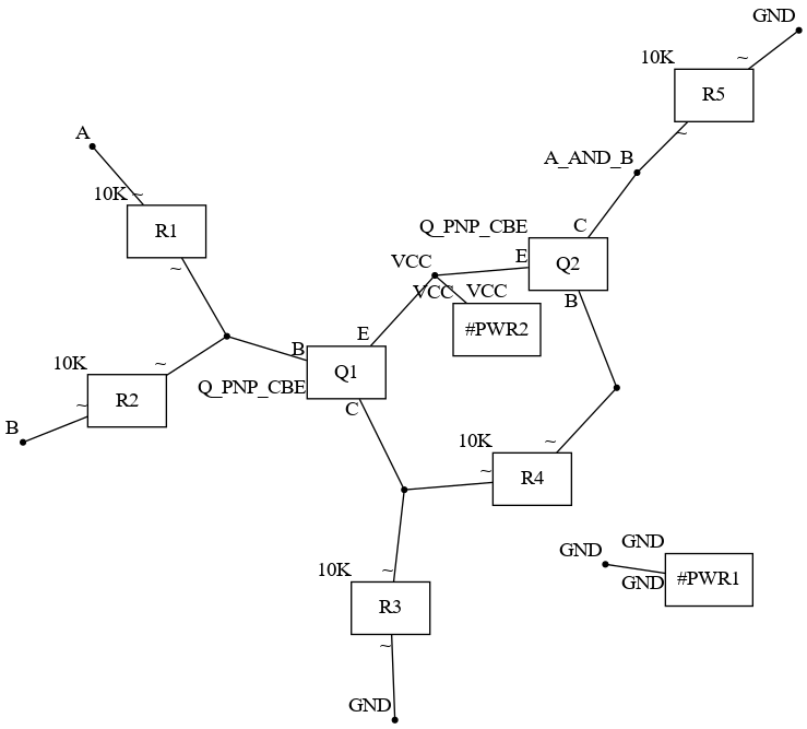
This graph might serve as a sanity-check for a small circuit, but you can imagine what it would look like if it included microcontrollers or FPGAs with hundreds of pins!
SVG Schematics#
Note: Generating SVG schematics requires that you install a pre-release version of netlistsvg on your system:
npm install https://github.com/nturley/netlistsvg
You can create a more conventional schematic as an SVG file by appending the following to the end of the script:
generate_svg()
The resulting and_gate.svg file looks like this:
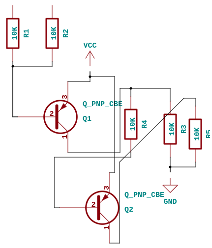
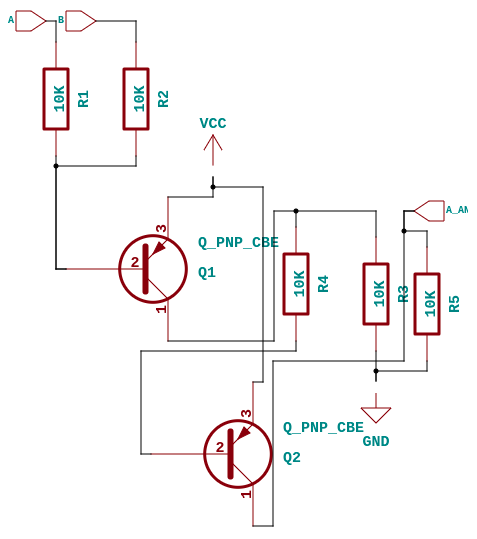
This uses the KiCad schematic symbols to create a better depiction of the circuit than the graph of the previous section, but it still lacks some things like the input and output terminals. To add these, modify the script as follows:
a.netio = "i"        # Input terminal.
b.netio = "i"        # Input terminal.
a_and_b.netio = "o"  # Output terminal.

generate_svg()
Now the schematic looks a little better:
The schematic can be further improved by adding some indicators about the “flow” of the signals through the components:
a.netio = "i"        # Input terminal.
b.netio = "i"        # Input terminal.
a_and_b.netio = "o"  # Output terminal.

q1.E.symio = "i"  # Signal enters Q1 on E and B terminals.
q1.B.symio = "i"
q1.C.symio = "o"  # Signal exits Q1 on C terminal.
q2.E.symio = "i"  # Signal enters Q2 on E and B terminals.
q2.B.symio = "i"
q2.C.symio = "o"  # Signal exits Q2 on C terminal.

generate_svg()
Now the schematic looks closer to the original:

In addition to the netio and symio attributes, you can also change the orientation of a part using the symtx attribute. A string assigned to symtx is processed from left to right with each character specifying one of the following operations upon the symbol:
symtx |
Operation |
|---|---|
H |
Flip symbol horizontally (left to right). |
V |
Flip symbol vertically (top to bottom). |
R |
Rotate symbol 90\(\degree\) to the left (counter clockwise). |
L |
Rotate symbol 90\(\degree\) to the right (clockwise). |
To illustrate, the following would flip transistor q1 horizontally and then rotate it 90\(\degree\) clockwise:
q1.symtx = "HR" # Flip horizontally and then rotate right by 90 degrees.
You can also set a net or bus attribute to choose whether it is fully drawn or replaced by a named stub at each connection point:
vcc.stub = True # Stub all VCC connections to parts.
The effects of setting these attributes are illustrated using the following code:
from skidl import *

# Create net stubs.
e, b, c = Net("ENET"), Net("BNET"), Net("CNET")
e.stub, b.stub, c.stub = True, True, True

# Create transistor part template.
qt = Part(lib="Device.lib", name="Q_PNP_CBE", dest=TEMPLATE)

# Instantiate transistor with various orientations.
for q, tx in zip(qt(8), ['', 'H', 'V', 'R', 'L', 'VL', 'HR', 'LV']):
    q['E B C'] += e, b, c  # Attach stubs to transistor pins.
    q.symtx = tx  # Assign orientation to transistor attributes.
    q.ref = 'Q_' + tx  # Place orientation in transistor reference.

generate_svg()
And this is the result:

Converting Existing Designs to SKiDL#
Currently, this feature is only available for KiCad designs.
You can convert an existing schematic-based design to SKiDL like this:
Generate a netlist file for your design using whatever procedure your ECAD system provides. For this discussion, call the netlist file my_design.net.
Convert the netlist file into a SKiDL program using the following command:
terminal netlist_to_skidl -i my_design.net -o my_design.py -w
That’s it! You can execute the my_design.py script and it will regenerate the netlist. Or you can use the script as a subcircuit in a larger design. Or do anything else that a SKiDL-based design supports.
SPICE Simulations#
You can describe a circuit using SKiDL and run a SPICE simulation on it. Go here to get the complete details.